Experimental research of the magnetic fluid converter
V.M.Polunin, J.J.Kameneva, V.V.Kovarda, A.G.Besedin, V.M.Paukov, M.V.Chistyakov
Kursk
State Technical University
Russia,
305040, Kursk, St. 50 years of October, b. 94
Tel:+7
(0712) 51-65-64
E-mail:
polunin_vm@hotbox.ru
The
article deals with the experimental research of the converter of sound
oscillations into electromagnetic the active element of which is the magnetic
fluid. The opportunity of functioning of magnetic fluid converter both in the
field of low sound frequencies (20 - 200 Hz) and in the field of frequencies
adjoining to the bottom border of an ultrasonic range (20 - 65 kHz) is shown.
Transformation in low-frequency field is carried out with the help of magnetic
fluid membranes, in high-frequency - on the acoustic-magnetic effect basis.
In the
field of low frequencies (20 - 200 Hz) the research has been made with the use
of magnetic fluid membranes (MFM).
As the
geometry of a free surface of a drop of magnetic fluid (МF) essentially depends
on the quantity and the degree of heterogeneity of a magnetic field [1], the
research of the magnetic field of the annular magnet used in device MFM has
been performed.
The
theoretical analysis of the magnetic field has been also carried out on the
basis of the model according to which the annular magnet is magnetized having a
constant of magnetization M on volume directed along its axis. Then components
of an induction of the magnetic field are defined by the formula B = -gmdu/
where the scalar potential looks like:
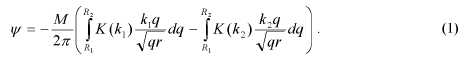
Here
![]()
R1,R2
- interior and exterior radiuses of the magnet, l - its half-thickness, K(k) -
elliptic integral of the first sort. Quantity of the
magnetization
was defined by value of the induction of the magnetic field measured in the
centre of the magnet.
On Figs.
1 а) and b) isolines according to axial Нz and radial Нr
components of the magnetic field are shown. The continuous line limits a
section of the field inside the tube.
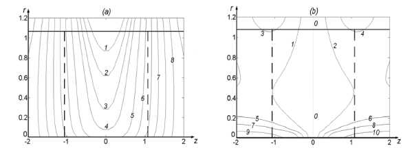
Fig. 1. а) isolines of the axial projection of an induction of a magnetic field: 1 - 90,2 - 86,3 - 81,4 - 77, 5 - 68,6 - 60,7 - 42,8-25 (mТl);b) isolines of the radial projection of an induction of a magnetic field: 1--3;2-3;3--7,4-7,5--7,6-7,7--10,8-10,9--23, 10-23; 11-0(mТl).
Thus, the
magnetic field in borders of the drop contour (dotted line) is mainly directed
along the axis of the annular magnet, i.e. the axial component of field Hz
is prevailing; in the radial direction small growth Hz is observed;
the radial component of field Hr is absent in plane z = 0 and tends
to increase in the vicinity of the axis.
The
approach of the "low-magnetic" environment accepted in [2-4], and
marked features of geometry of the magnetic field in a zone of an arrangement
of the crosspiece, testifying a determining role in ponderomotive elasticity
formation of the axial component of magnetic field Hz, are used for
calculation of ponderomotive elasticity factor [5].
In the
methodical attitude one of the most important questions is the establishment of
borders of a dynamic range. An experiment with magnetic fluid membrane (МFМ)
has been made to find the latter; its device being described in [4]. Magnetic
fluid crosspiece blocks the section of the tube being the neck of the glass
flask in volume 0,5 l. At rise of the flask on height Az above a support and
its fixation in this position by soft pressing, the crosspiece is displaced
concerning the position of equilibration on 5z, that is
![]()
here kg-
elasticity of the gas cavity, kp- elasticity of ponderomotive type.
At sharp
returning the flask in a starting position due to inertness the crosspiece
appears to be displaced concerning the position of equilibration, it
predetermines the development of the oscillatory process. At the moment of
passage of position of equilibration by the crosspiece maximum value EMF- em
is fixed. Sharp moving of the flask is achieved under the influence of the
impact. MF used in mechanical engineering, representing the colloid solution of
one-domain particles of magnetite Fe3O4 in kerosene (МF-1
and МF-2) are applied. Physical parameters of magnetic colloids are shown in
Table 1.
Table 1
|
Sample |
p, kg/m3 |
ns,
Pa-s |
Ms,
kА/m |
X |
|
МF-1 |
1294 |
3,2-10-3 |
52±1 |
6,2 |
|
МF-2 |
1499 |
8Д-10-3 |
60±1 |
7,5 |
Here: p -
is density MF, % - an initial magnetizability, rjs - colloid static
shift viscosity. The listed parameters were defined by standard methods.
On Fig. 2
the dependence em(Az) received for MFM on the basis of colloid MF-2
is shown. Under the conditions of the given experiment the height of the cargo
falling h '=20,3 mm. Temperature is Т=21±0,5°С. Linear approximation is
executed with the use of the program MS Excel. At Az > 3,5 mm for MF-2 and
Az > 4,5 mm for MF-1 backlog of dependence 8m(Az) from the linear
is observed.
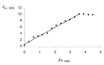
Fig. 2. Dependence sm(Az)
Let's term device (3 - a tangent of an angle of an
inclination of an approximated line as sensitivity (to displacement), and value
of first oscillation's amplitude at Az=0 as the initial impulse £mo.
In Table 2 values (3 and £mo, received from the experiment
with various height of the cargo falling h'are shown.
Table 2
|
Colloid |
h', mm |
P, mV/mm |
£mo, mV |
Colloid |
h ',mm |
m/h', mV/mm |
sm0, mV |
|
МF-1 |
9,0 |
4,64 |
0,5 |
МF-2 |
10,8 |
2,53 |
0,75 |
|
14,6 |
4,88 |
0,5 |
20,3 |
2,62 |
0,50 |
||
|
19,4 |
5,32 |
0,5 |
|
|
|
The
parameter (3 increases almost in 2 times if to use colloid MF-1 instead of more
concentrated colloid MF-2. It is possible to assume, that the specified result
is caused by the negative role of viscous friction's forces due to which the
amplitude of initial displacement of the crosspiece from the position of
equilibrium at the moment of drawing of impact is decreased.
In the
field of high frequencies (20 - 65 кHz) research
was made on the acoustic-magnetic effect basis (АМE) [6]. The diagram of an
experiment on studying АМE in a rotating magnetic field is shown in Fig.3.
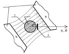
Fig. 3. The diagram of experiment
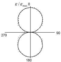
Fig. 4. Dependence of relative amplitudes АМE on angle
Dependence
of amplitude induced by EMF on the angle c in relative units is presented in
Fig.4. The thin line shows the graphic cos.
Let's
receive the ratio describing dependence of amplitude АМE upon the angle <p,
limited to a case when the flat monochromatic wave along the axis of tube 2 is
extended in МF 1. The axis of the tube is located vertically. The length of the
wave exceeds radius of the tube Л » R and R > >S . The induction coil 3 has geometry of a
rectangular and is in closed proximity to an external surface of a tube with an
air-gap so there is an opportunity of free moving. The normal to a frame nr in
its center passes through the axis of the tube. The permanent magnet 4 is
installed giving an opportunity of rotation around the axis of the tube.
The
magnetic flux through a circuit, containing N
turns, can be written down as follows
![]()
where S -
the average area of a turn, B - a vector of a magnetic induction, nr - an
individual normal to a plane of a circuit.
As
![]()
and
![]()
where M -
magnetization, and R - demagnetization factor,
![]()
Amplitude
EMF, induced in a circuit:
![]()
Thus,
during only one revolution of a magnet the amplitude, following the change of
cos <p,
accepts
the maximum value twice and is twice equal to zero.
Fig.5
presents curve 1 - experimentally received dependence of the cross component to
the tube of magnetic intensity upon distance along the axis; curve 2 -
dependence EMF of an induction s on the distance measured along the axis of the
tube.
The
dependence of amplitude EMF of an induction s0 on amplitude of a
voltage of variable EMF going to piesoelement U is shown in Fig.6.
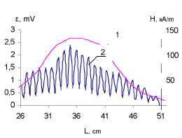
Fig. 5. Dependences H(L) - curve 1 and s(L) - curve 2.
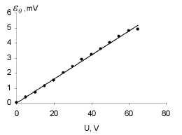
Fig. 6. Dependence s0 (U) .
REFERENCES
- Rosensweig R.E.
Ferrohydrodynamics. // Cambridge: Univ. Press. 1985. P.344.
- Karpova G.V., Lobova O.V.,
Postnikov E.B., Polunin V.M., Roslyakova L.I. Elastic properties of
magnetic fluid sealants // 11-th sessions Russian Acoust. Soc.: Col.
Scientific. work.- Moscow. 2001. V.2. pp. 203 - 207.
- Karpova G.V., Lobova O.V., Polunin
V.M., Postnikov E.B., Zubarev E.K. Resonance properties of magnetic fluid
sealants // Magnetohydrodynamics. 2002. V.38, №4, pp. 385 - 390.
- Karpova G.V., Lobova O.V.,
Paukov V.M., Polunin V.M., Postnikov E.B.. An experimental research of
magnetic fluid resonator// Acoust. Journ. 2002. V.48. №3. pp. 364 - 367.
- Baglikov S.J., Karelin A.V.,
Karpova G.V., Kovarda V.V., Polunin V.M., Chistyakov M.V.. Results of an
experimental research of magnetic-elastic properties of a magnetic fluid
// 13-th session Russian Acoust. Soc.: Col. Scientific. work - Moscow.
2003. V.1. pp. 193 - 196.
- V.M.Polunin. The
electromagnetic effects caused by elastic deformation of a cylindrical
sample of the magnetized fluid // Magnetohydrodynamics. 1988. №3. pp. 43 -
50.